
NT Series Actuators-TYPE
EVOLUTION IN ENGINEERING RACK & PINION ACTUATORS.
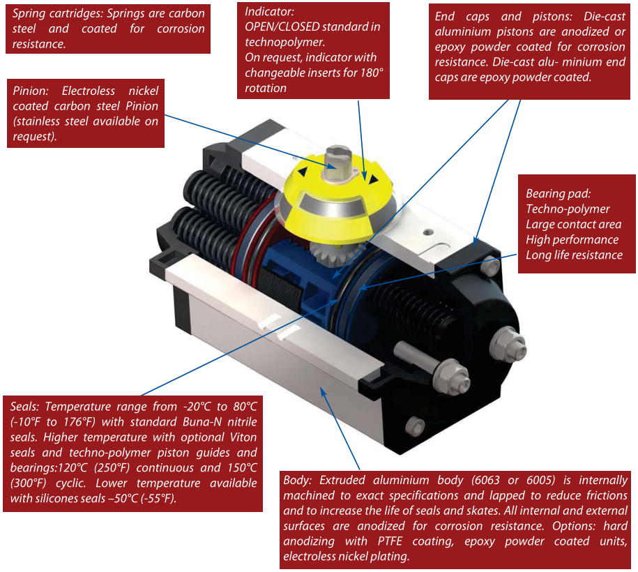
GENERAL FEATURES
• The NSEC rack & pinion pneumatic actuator produces linear torque output in a compact designutilizing the same body and end caps for double acting and spring return units.
• Namur VDI/VDE 3845 and ISO 5211 dimensions on all sizes. No special blocks are required tomount solenoid valves, limit switches or positioners.
• The standard angle of rotation is 90°. Additional travel rotations of 120°, 135°, 150° and 180° areavailable. All sizes feature a travel stop with ± 10° in both open and close directions.
• The female pinion drive is standard with a double square output drive, and optional with a double-D drive, keyed drive and designs to meet your specific requirements.
• Shaft bearings isolate the pinion gear from the housing and support the shaft for high cycleapplications.
• The pinion teeth are engaged for the full length and stroke of the piston.
• The pinion height allows manual override without disturbing the indicated positions.
• External open/closed indicator is standard, available indicators for all the rotations.
• Pistons incorporate double wear pads to separate the rack from the actuator wall and serve asboth guide and wear bearings.
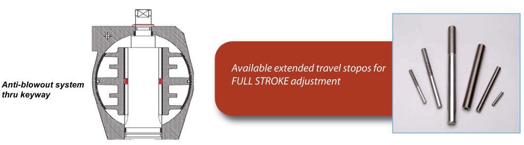
• NT series pinion feature a keyway as anti-blowout system.
• All internal and external components are treated to increase corrosion resistance.
• Epoxy coated special steel springs are pre-loaded.
• The stainless steel end cap fasteners are extra long to allow for spring relaxation. All parts are corrosion resistant.
• Air pressure operation from 2 to 10 Bar (40 – 150 PSI). Water, nitrogen and compatible hydraulic fluids may also be used to power the actuator.
• All external fasteners are corrosion resistant stainless steel.
• All units are permanently lubricated at the factory with non-silicone grease.
• All units are externally stamped with a progressive traceable serial number.
• 100% of all units are factory pressure leak tested, and individually boxed for shipment.
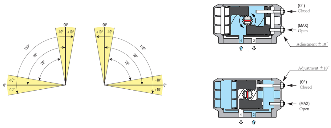
BI-DIRECTIONAL PATENTED TRAVEL STOP ILLUSTRATION
NT actuators feature a bi-directional travel stop. Side located stops allow a ± 10° adjustment
- BEST IN THE MARKET - in both closing and opening directions, so guarantee a range of adjustment between 70°and 110° of actuator stroke.
Travel stops are designed to absorb the maximum rated torque of the actuator and the maximum impact load associated with recommended speed stroke.
To increase pistons resistance both travel stops arrest the pistons in their part with the largest mass of material.
Adjustment of the counter clockwise and clockwise rotation is accomplished by turning the respective left (MAX) and right stop (0°) adjustment screws to increase or reduce output rotation.
OPTIONAL: extended travel stops for FULL STROKE adjustment
GENERAL STRUCTURE
ANTI-BLOWOUT SYSTEM OF THE PINION
The anti-blowout system of the pinion is ensured thru a double protection: both with an upper c-clip and twokeyways casted on the pistons. In case of unusual downward movement of the pinion, the keyways will interphere with the grooves on the pinion and therefore stopping it.
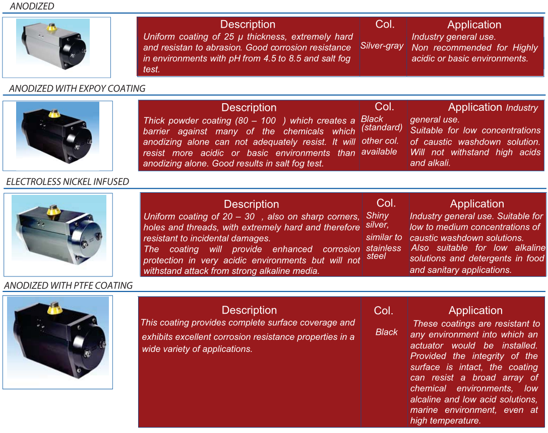
SPECIAL COATINGS
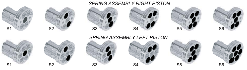
SPRING ASSEMBLY
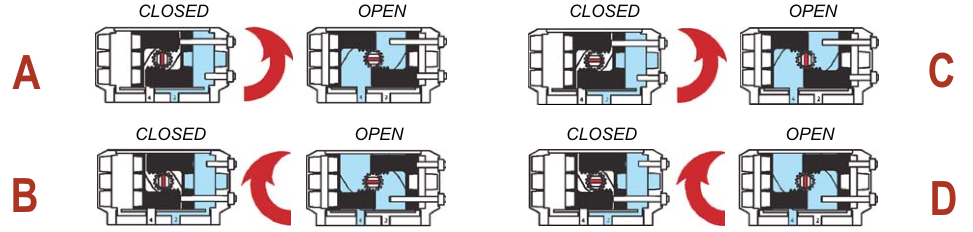
MOUNTING VARIATIONS
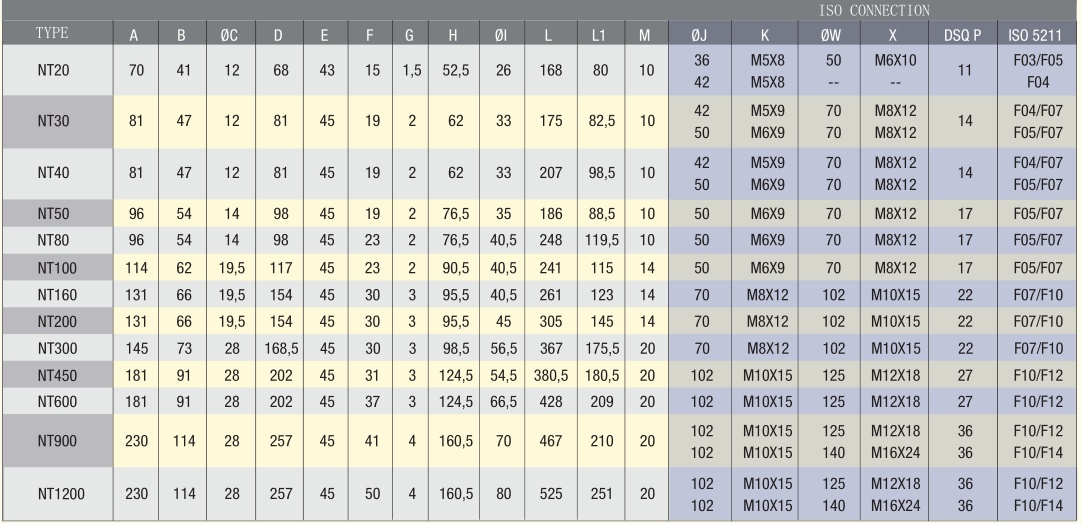
TECHNICAL DATA
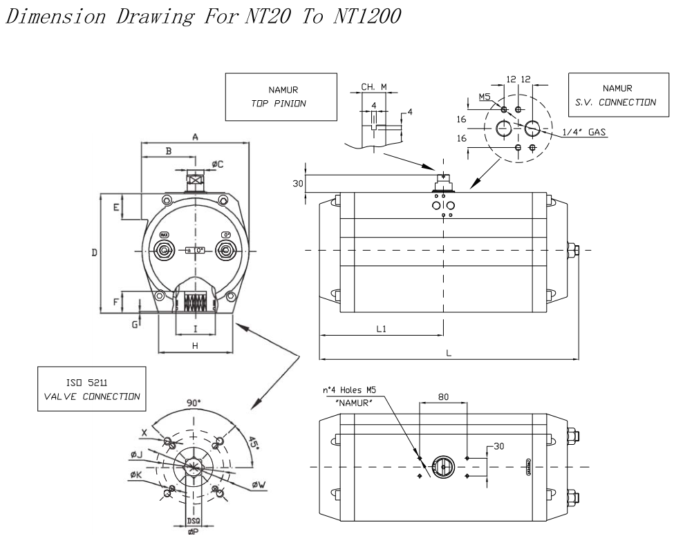
DIMENSION